Living most of my life in Upstate New York (and briefly in Northern Vermont), I developed a fond appreciation for merino wool, down jackets, seat heaters, and auto starters.
Unfortunately, I spent most of my bitter cold winters without these any of these. When I got my first real job out of college, I bought my first car with seat heaters, and I decided it was time for a car starter. Unfortunately, my desk was about a 20 minute walk through a very concrete building; too far and dense for the usual low power, off the shelf 433MHz transceiver.
The other problem in creating my own was to create something safe and functional to actually start the car. My attempts to sniff and decipher the CAN bus were met with defeat, and I didn't really like the idea of spamming the central nervous system of my car with commands that I thought would work.
I began to draw up a slightly more mechanical version, using transistors to fire relays which replicate the push button start. I drove around a parking lot a few times to be sure the the push to start and kill switch were disabled while in drive before attempting to automate it.
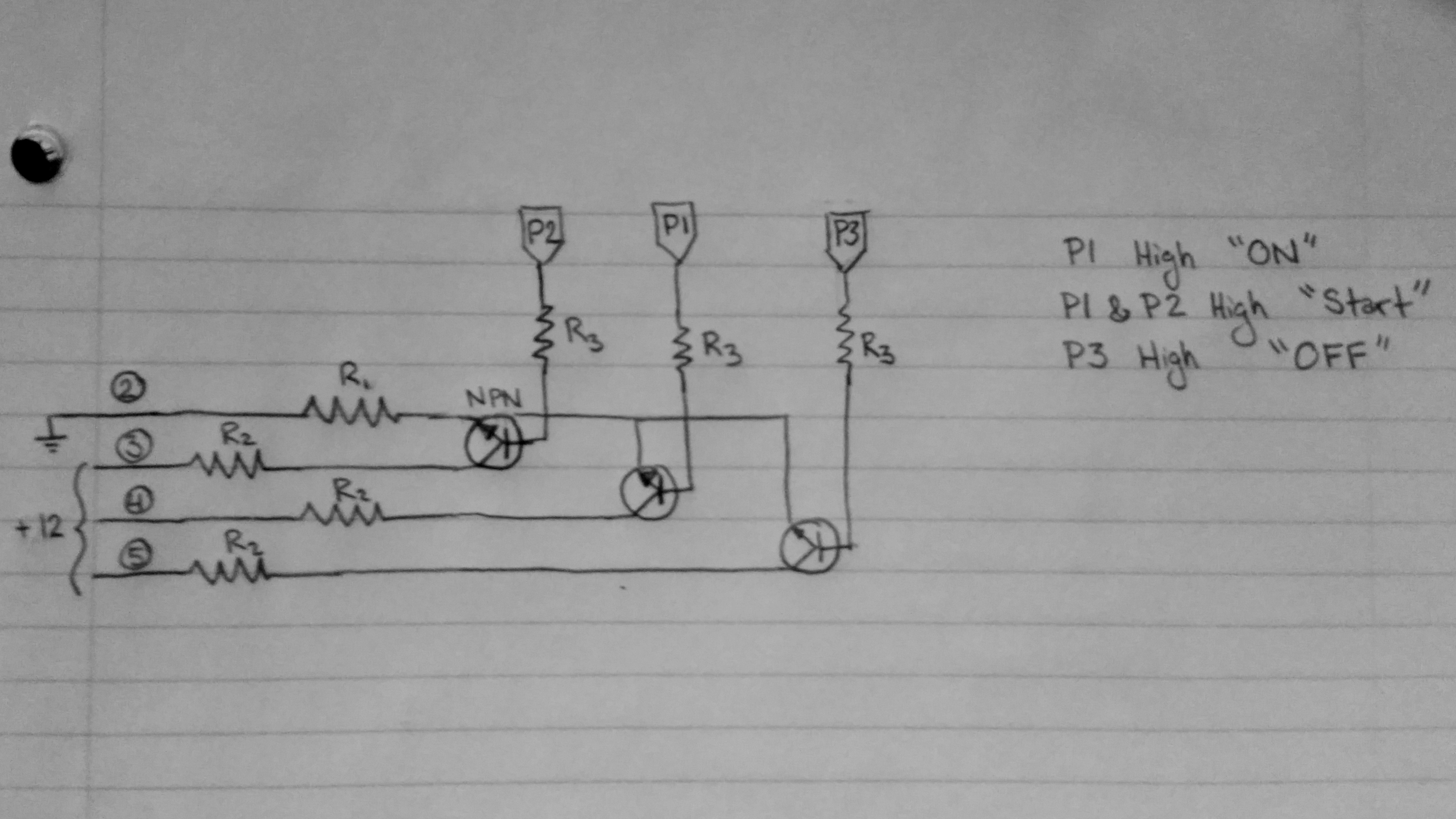
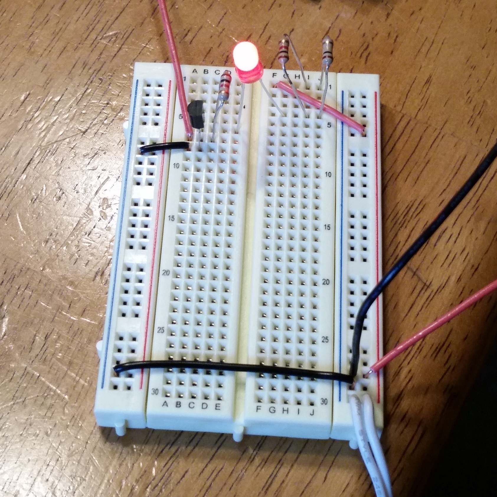
I setup a basic circuit with a transistor and LED on a breadboard to check that things were working. Most of my debugging time was spent trying to get the correct AT GSM syntax sent to the GPRS Shield (v1.4 made by Seeed Studio) running on top of a Arduino Uno. SparkFun has a helpful reference document with a pretty comprehensive list of commands.
Below is the short script I ended up debugging with, to grab the sms messages from the modem and flash an LED.
#include <SoftwareSerial.h>

char inchar; // Will hold the incoming character from the GSM shield
SoftwareSerial SIM900(7, 8);

int led = 13;

void setup()
{
  Serial.begin(19200);
  // set up the digital pins to control
  pinMode(led, OUTPUT);
  digitalWrite(led, LOW);

  // wake up the GSM shield
  SIM900.begin(19200);
  delay(20000); // give time to log on to network.
  SIM900.print("AT+CMGF=1\r"); // set SMS mode to text
  delay(100);
  SIM900.print("AT+CNMI=2,2,0,0,0\r");
  // blurt out contents of new SMS upon receipt to the GSM shield's serial out
  delay(100);
  Serial.println("Ready...");
}

void loop()
{
  //If a character comes in from the cellular module...
  if(SIM900.available() >0)
  {
    inchar=SIM900.read();
    if (inchar=='#')
    {
      delay(10);

      inchar=SIM900.read();
      if (inchar=='a')
      {
        delay(10);
        inchar=SIM900.read();
        if (inchar=='0')
        {
          digitalWrite(led, LOW);
        }
        else if (inchar=='1')
        {
          digitalWrite(led, HIGH);
        }
        delay(10);
        // SIM900.println("AT+CMGD=1,4"); // delete all SMS
      }
    }
  }
}
Success!
Once I got the LED version working, I wired the rest of the transistors and dug up some spare relays to test it out in the car.
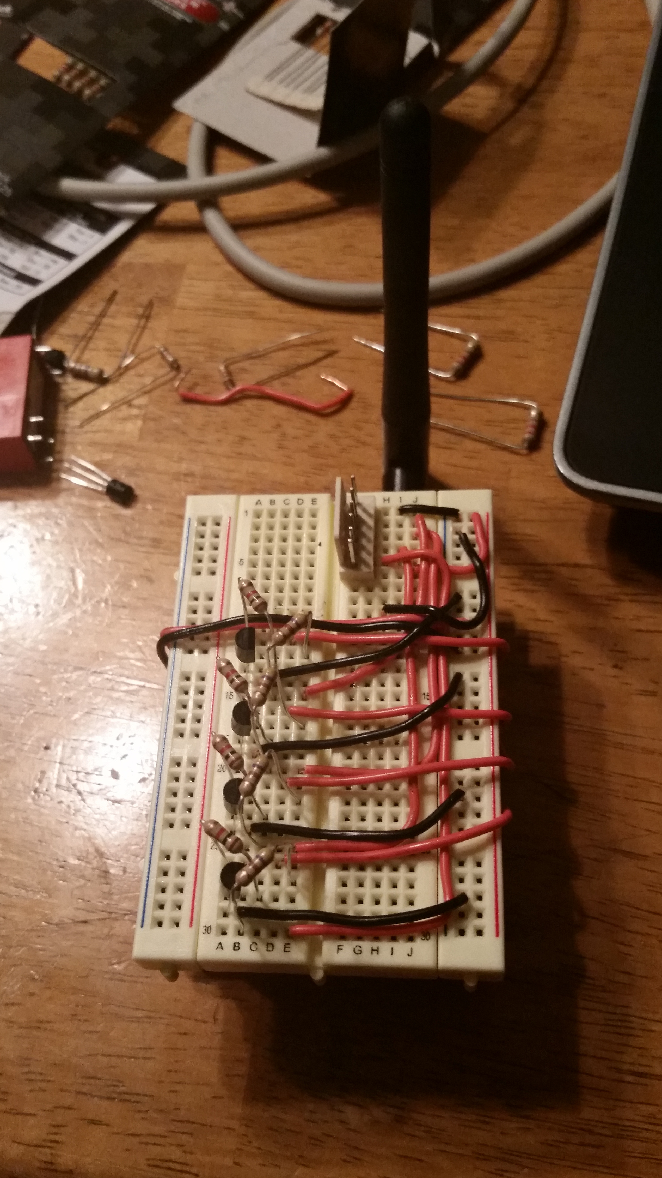
I had to adjust all my neat wiring to get the relays to fit... but at least it wasn't solder.
I needed to add a fourth circuit to active the brake switch before the car would start. There's an error counter in the ECM that will disable the push to start after 10 cycles if the brake light switch is activated but a pressure limit switch isn't activated in the master cylinder, but some things are better let alone. Simply using the brakes once after the auto start resets the counter. Some updates to the code to perform the actual start stop functions were added.
/*
CarStarter V0.1
24NOV2014
 */

#include <avr/wdt.h>
#include <SoftwareSerial.h>
wdt_reset();

char inchar; // Will hold the incoming character from the GSM shield
SoftwareSerial SIM900(7, 8);

unsigned long StartTime;
unsigned long OnTime = millis();
boolean OnStatus=false;

int phone_number = 5558675309
int hours = 0;
int StopPin = 2;
int StartPin = 3;
int Brake = 4;
boolean debug = false;

// the setup function runs once when you press reset or power the board
void setup() {
  watchdogSetup();
  wdt_reset();
  // wake up the GSM shield
  if(debug){
    Serial.begin(19200);
  }
  else{
    SIM900.begin(19200);
    delay(5000);
    SIM900.print("AT+CPOWD=1\r"); // Turn off modem if it's on
    wdt_reset();
    delay(5000);
    wdt_reset();
    ModemPower();//Turn On Modem
    wdt_reset();
    delay(5000);
    wdt_reset();
    SIM900.print("AT+CMGF=1\r"); // set SMS mode to text
    SIM900.println("AT+CMGD=1,4"); // delete all SMS (Don't want to accidentally start car)
    delay(100);
    SIM900.print("AT+CNMI=2,2,0,0,0\r");
    // blurt out contents of new SMS upon receipt to the GSM shield's serial out
    delay(100);
    //SIM900.println("AT+CMGD=1,4"); // delete all SMS (Don't want to accidentally start car)
    delay(100);
  }
  // initialize pins
  pinMode(StartPin, OUTPUT);
  pinMode(StopPin, OUTPUT);
  pinMode(Brake, OUTPUT);
  digitalWrite(StartPin, LOW);
  digitalWrite(Brake, LOW);
  wdt_reset();
  StopCar();
  wdt_reset();

}

void loop() {
  wdt_reset();
  if(debug){
    //If a character comes in from the cellular module...
    if(Serial.available() >0)
    {
      inchar=Serial.read();
      if (inchar=='O')
      {
        wdt_reset();
        delay(50);
        wdt_reset();
        inchar=Serial.read();

        if (inchar=='f'){
          StopCar();
        }

        else if (inchar=='n'){
          StartCar();
        }
      }
    }
  }
  else{
    //If a character comes in from the cellular module...
    if(SIM900.available() >0)
    {
      inchar=SIM900.read();
      if (inchar=='O')
      {
        wdt_reset();
        delay(50);
        wdt_reset();
        inchar=SIM900.read();

        if (inchar=='f'){
          StopCar();
        }

        else if (inchar=='n'){
          StartCar();
        }

        delay(50);
        SIM900.println("AT+CMGD=1,4"); // delete all SMS
      }
    }
  }
//    if(debug){
      wdt_reset();
//      Serial.println(((millis()-OnTime)/1000-10*minutes)%1);
      if((millis()/3600000-hours)%4>3){
        hours = hours + 4;
        //Serial.println(minutes);
        //if(hours>24){
          //Daily restart
          //delay(30000);
        //}
        String OutStr = "Hours Running: ";
        wdt_reset();
        OutStr += hours;
        SendResponse(OutStr);
      }
    //}

    if(OnStatus && millis()-StartTime>=600000){
      wdt_reset();
      StopCar();
      OnStatus=false;
    }
}

void StartCar(){
  // Create a Reference time
  StartTime = millis();
  // Turn on Brake Switch
  digitalWrite(Brake, HIGH);   // turn the LED on (HIGH is the voltage level)
  wdt_reset();
  delay(1000);
  // Turn on Start
  digitalWrite(StartPin, HIGH);   // turn the LED on (HIGH is the voltage level)
  wdt_reset();
  delay(2000);
  // Release Start & Brake
  digitalWrite(Brake, LOW);   // turn the LED on (HIGH is the voltage level)
  digitalWrite(StartPin, LOW);   // turn the LED on (HIGH is the voltage level)
  SendResponse("Car Started");
  OnStatus = true;
}

void StopCar(){
  //------------------------------- Kill Ignition --------------------------
  digitalWrite(StopPin, HIGH);   // turn the LED on (HIGH is the voltage level)
  wdt_reset();
  delay(1000);              // wait for a second
  digitalWrite(StopPin, LOW);   // turn the LED on (HIGH is the voltage level)
  wdt_reset();
  delay(1000);
  //---------------------------- Turn Everything Off -----------------------
  digitalWrite(StopPin, HIGH);   // turn the LED on (HIGH is the voltage level)
  wdt_reset();
  delay(1000);
  digitalWrite(StopPin, LOW);   // turn the LED on (HIGH is the voltage level)
  wdt_reset();
  delay(1000);
  //---------------------------- Engage Steering Lock ----------------------
  digitalWrite(StopPin, HIGH);   // turn the LED on (HIGH is the voltage level)
  wdt_reset();
  delay(3000);
  digitalWrite(StopPin, LOW);   // turn the LED on (HIGH is the voltage level)
  wdt_reset();
  delay(1000);
  SendResponse("Car Stopped");
}

void SendResponse(String InputText){
  wdt_reset();
  if(debug){
    Serial.println(InputText);
  }
  else{
    wdt_reset();
    //send sms message, +1 is the Country Code
    SIM900.println("AT + CMGS = \"+1"+phone_numnber+"\"");
    wdt_reset();
    delay(100);
    wdt_reset();
    SIM900.println(InputText);//the content of the message
    wdt_reset();
    delay(100);
    wdt_reset();
    SIM900.println((char)26);//the ASCII code of the ctrl+z is 26
    wdt_reset();
    delay(100);
    wdt_reset();
    SIM900.println();
    wdt_reset();
  }
}

void ModemPower()
{
  pinMode(9, OUTPUT);
  digitalWrite(9,LOW);
  wdt_reset();
  delay(1000);
  digitalWrite(9,HIGH);
  wdt_reset();
  delay(2000);
  digitalWrite(9,LOW);
  wdt_reset();
  delay(3000);
  wdt_reset();
}

void watchdogSetup(void)
{
cli(); // disable all interrupts
wdt_reset(); // reset the WDT timer
/*
 WDTCSR configuration:
 WDIE = 1: Interrupt Enable
 WDE = 1 :Reset Enable
 WDP3 = 1 :For 8000ms Time-out
 WDP2 = 0 :For 8000ms Time-out
 WDP1 = 0 :For 8000ms Time-out
 WDP0 = 1 :For 8000ms Time-out
*/
// Enter Watchdog Configuration mode:
WDTCSR |= (1<<WDCE) | (1<<WDE);
// Set Watchdog settings:
 WDTCSR = (1<<WDIE) | (1<<WDE) | (1<<WDP3) | (0<<WDP2) | (0<<WDP1) | (1<<WDP0);
sei();
}

ISR(WDT_vect) // Watchdog timer interrupt.
{
  SendResponse("Watchdog Bit");
// Include your code here - be careful not to use functions they
// may cause the interrupt to hang and prevent a reset.
}
I found that I could power a spare key fob off the pins driving the transistors, which allowed the car to start without needing to leave the car unlocked with a key inside (well, without an accessible key). Without power to the key, the car wouldn't start, and would auto lock. Note the addition of a watchdog here; if the watch dog bites the modem is reinitialized and the stop command is sent to the car, so that the car isn't accidentally left running.
Success!

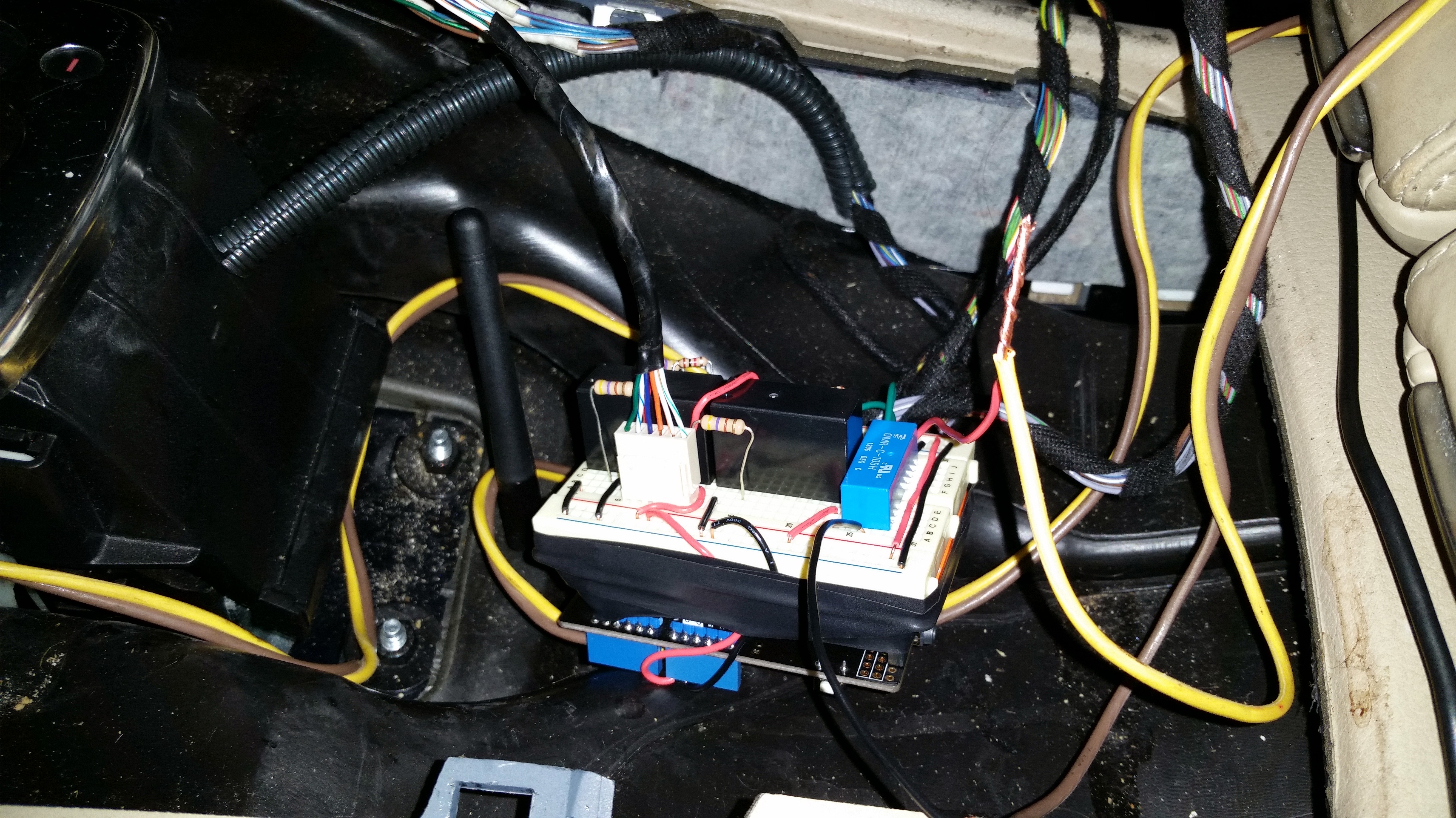
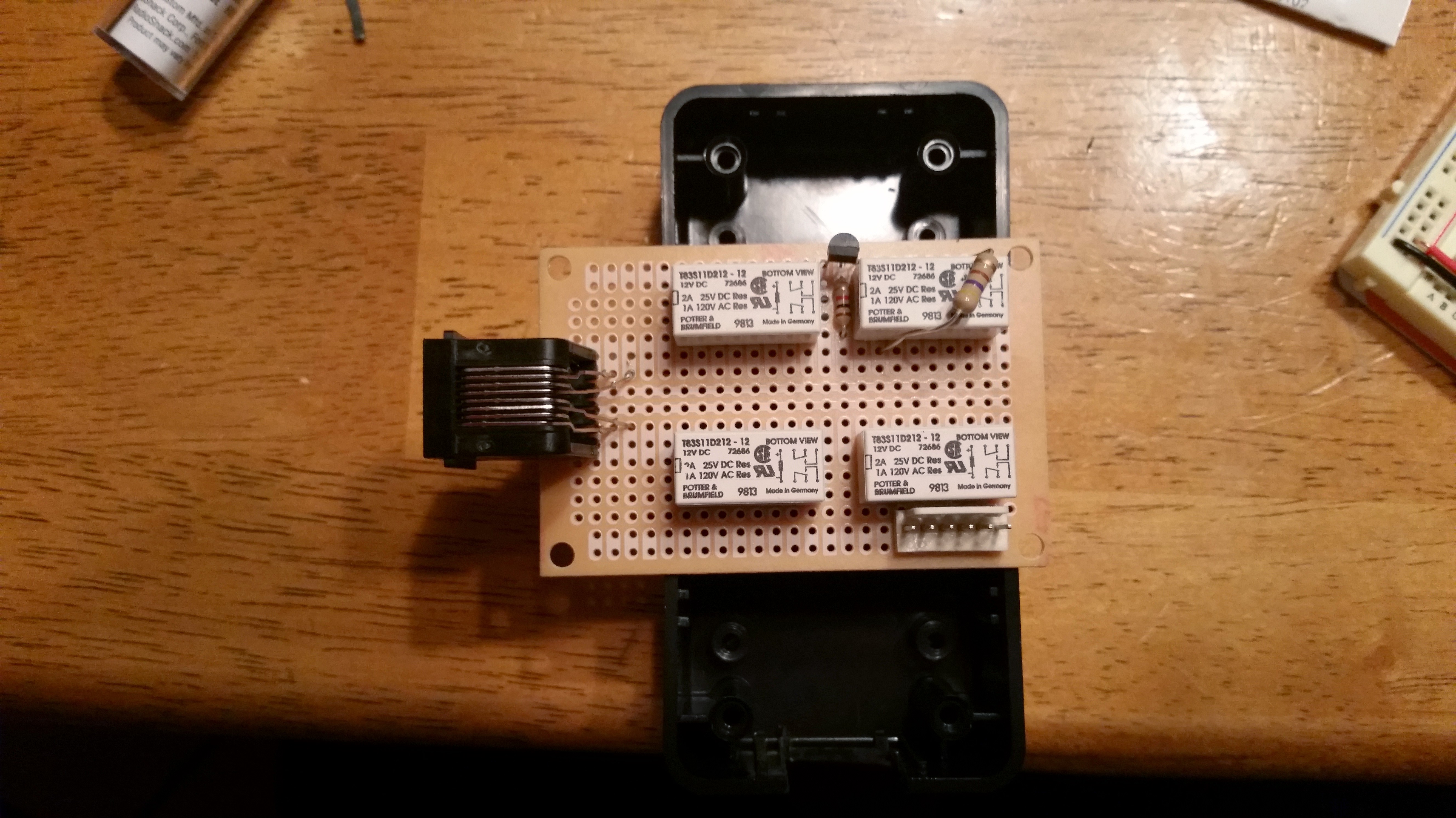
After a successful but cold test run and a few days of driving around with the center console torn apart, I decided I needed to make something slightly more permeant. I purchased a few of the correct sized relays, and built a protoboard into a project enclosure. I used an ethernet jack to provide a quick disconnect for the growing number of wires, which was quite helpful for debugging outside of the freezing car.
I did find a rather undesired failure mode after a few days of driving. My checks to be sure the kill switch was disabled while the vehicle was in drive were a little over presumptuous. I tested the car in drive while moving, however hadn't tried stopped with the car in drive. While crossing a parking lot and stopping to let a pedestrian by, the AC compressor kicked on for the defrost, which coupled with a low idle created a enough of a power dip to restart the Arduino, triggering the initialization sequence and shutting down the car. Thinking I was smart, I hadn't brought my normal set of keys, so I frantically pulled my cell phone from my pocket to send the restart command and then waited painstaking milliseconds for the engine to start, while a growing line of frustrated shoppers started to build up behind me. Lesson learned, power conditioning is absolutely necessary, and was quickly added.